Vectrex Service Manual
I - VECTREX SPECIFICATIONS
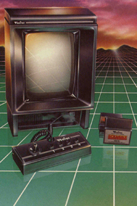
The VECTREX Is a self-contained, microprocessor based, Vector
Display, portable home video game arcade with external game cartridge
program capability.
| MPU |
68A09 |
8K X 8 BIT DATA - 16 BIT ADDRESS |
Please note:
INTERNAL ROM 2114 (2)
should read:
INTERNAL RAM 2114 (2) |
| INTERNAL ROM |
2363 |
8K X 8 BIT |
| INTERNAL RAM |
2114(2) |
1K X 4 SIT (ea.) |
| EXTERNAL ROM |
(GAME CARTRIDGE) |
8K X 8 BIT CAPABILITY |
CRT display: SAMSUNG 240RB40 90 DEG. DEF. B&W VECTOR DEFLECTION
12 EXTERNAL GAME CARTRIDGES CURRENTLY (ps: and many more today)
1 RESIDENT GAME: Mine Storm
Game Cartridges include a screen overlay
Second Controller available as an accessory
120V AC - 60HZ (USA ) or 220V - 50 Hz (Europe)
DIMENSIONS: 9 3/4 X 11 1/2 X 14 1/2
WEIGHT: 15 Lbs.
II - VECTREX OPERATION INSTRUCTIONS
When you remove your Vectrex Arcade System from the box you should have these items:
IMPORTANT - To prevent overheating, never block the ventilation openings on the back or bottom of the console. These openings have been designed to provide
proper ventilation during operation and should not be enclosed or covered in
any way.
Before inserting the plug. make sure the console switch is OFF. The unit will work in a 120 Volt AC 60 Hz (in USA) or 220 Volt - 50 Hz (in Europe) electrical outlet depending on the model version of the Vectrex. Using any other power supply will damage the unit. As a special safety feature, the plug is polarized so that it will fit into standard AC outlets in one direction only (on US models). If the plug does not slip easily into the outlet, turn it over and insert again.
Setting Up the Vectrex
Your Vectrex Arcade System is designed for table-top use. For the most enjoyment, select a location where the screen will be at about eye level when you are playing the games. A sturdy table, desk or shelf is suggested. Do not operate console on a bed, sofa, carped, etc.
Control Panel Storage
To remove control panel from storage area at the bottom of the console, press the release tab and the panel will drop down. To return control panel to its storage area:
- Coil the cord once around the joystick and then on top of the action buttons
- Slide the panel onto the tabs at the bottom of the console
- Flip up the panel until it clicks into place
Inserting and removing game cartridges
Important: To prolog the life of your Vectrex Arcade System and protect the electronic components, the console should be turned OFF when inserting and removing game cartridges!
To insert a cartridge
- Make sure the console´s power is turned OFF
- Hold the cartridge with the label side up
- Insert cartridge carefully into the slot on the right side of the console
- Be sure the cartridge is firmly inserted to the guideline marked on the cartridge
To remove a cartridge
- Make sure the console´s power is turned OFF
- Pull the cartridge straight out of the slot
- To protect the electronic components, the cartridge should be stored in the original package or other suitable container
IMPORTANT - Unlike a conventional TV screen, the screen build into the Vectrex console uses an advanced display technology to achieve brilliant clear images and special visual effects like rotation and zooming. Due to this special display technology, it may appera that the images pulse slightly. THIS SLIGHT PULSING IS NORMAL AND DOES NOT INDICATE A PROBLEM WITH YOUR CONSOLE. The screen overlays that are provided with each cartridge have been specially designed to virtually eleminate the slight pulsing. ps by the curator: If you have a bug and you can´t fix it - call it a feature 
Inserting and Removing Screen Overlays
To insert Screen Overlay
- Slip the bottom of the screen overlay behind the two tabs at the bottom of the screen
- Push the top of the overlay down slightly using the finger area at the top and press against the tabs at the top until the overlay snaps into place under the tabs.
To remove Screen Overlay
- Place you finger in the curved area at the top of the overlay, press down slightly and pull the overlay straight out
- Store the overlay in the original package or other suitable container
Starting Game Play
- Make sure the cartridge and the screen overlay are inserted properly.
NOTE: A cartridge is not needed to play Mine Storm, which is the game build into the console
- Turn the ON/OFF/VOLUME CONTROLL to the ON position (clockwise). You will see the Vectrex title (bootscreen) for a few seconds, then the name of the game.
- Adjust the volume controll to the desired listening level
- Refer to the individual game instructions for game play details
III - MAINTAINANCE AND SAFETY TIPS
Your Vectrex Arcade System will bring you many years of fun and excitement (ps: they where right...!) In order to keep your Vectrex in good condition, please remember the following:
- Proper ventilation is very important to prevent overheating. Never block the ventilation openings on the back of the console in any way. There are also ventilation slots on the bottom which should not be blocked by placing the Vectrex on a bed, sofa, carped, etc.
- Be careful not to spill liquids on the console, cartridges or control panel and never expose the unit to rain or excessive moisture. If this happens, unlug the console, wipe the outside dry, and then let air dry for at least 48 hours before using it again.
- Do not expose the console, cartridgres or control panel to excessive or extreme heat.
Never place the unit near or over a radiator or heat system.
- Never remove the back cover of the console or drop or push objects through the slots in the back cover.
This could expose you to very high voltage!
- If the Vectrex is damaged, shock hazard may exist. If damaged or there is a distinct change in performance, immediatly unplug the console and have it checked by a GCE Authorised Service Dealer
(ps: today an elderly TV technican may can help you)
- Care should be taken not to drop the Vectrex, cartridges or control panel. The console should be liftet using the convenient handle at the upper rear of the console.
- Always turn power OFF when the unit is not in use and before inserting or removing cartridges. Do not plug into a power source other than 120 Volt AC 60 (USA) / 220/240 Volt (Europe)
- Clean the screen overlays ant the exterior of the Vectrex with a soft, slightly dampened cloth. Before cleaning the console, make sure the unit has been turned OFF and the power cord has been disconnected.
Never use household cleaner, cleanser or spay on the overlays or Vectrex.
V. CIRCUIT DESCRIPTION
As a general description, the MP3000 is a self-contained video
game system intended for home use. The system includes its own
9" B&W monitor screen and 3" permanent magnet speaker.
ROM type cartridges are available offering arcade type video and
sound game play. No external TV receiver hookup is needed or provided
for. A front panel storable controller allows control over the
game via joystick and push button action switches. For two player
operation a second controller Identical to the single player controller
is available as an accessory product. Both controllers attach
to the main game console through nine wire coiled telephone style
cables. There is a consumer power switch/volume control on the
front panel as well as a game reset button. A consumer adjustable
brightness control is located on the main console rear housing.
For the technical description which follows, the reader is encouraged
to refer to the block diagram and schematic.
The HP3000 is a microprocessor based, vector scan system using
a standard 9" black & white CRT as its video display device. The
microprocessor (MPU) is the Motorola 66A09 device. The MPU operates
at 1.6 MHz from a 6 MHz external Xtal. An Internal divide by 4
circuit generates the MPU 1.6 MHz "E" clock signal used in the
system. Program memory is stored in the 8K x 8 bit 2363 type ROM.
This ROM contains common subroutines. the "executive" or assembler
instructions plus one complete game.
Two 1 K x 4 bit 2114 type static. RAMS provide storage locations
for data indicative of locations of objects, game status, and
various other information needed by the microprocessor during
game operation. Peripheral Interface Adaptor (PIA) Chip, has two
8 bit peripheral ports which interfaces the MPU with peripheral
devices and external signals. One of the PIA ports Interfaces
the General It Instrument AY-3-8912 sound-1.0. chip with the MPU
and also drives the digital to analog converter hip MC1408. The
other PIA port is used as control lines for the sound chip. selector
control for the multiplex chip and as a means to read the A/D
comparator that's used in the joystick successive approximation
circuitry. Sound is either MPU generated directly or by use of
the AY-3-8912 sound chip.
The AY-3-8912 sound chip is a programmable sound generator containing
3 tone generators and wave shaping circuitry. This chip also has
a single 8 bit 1.0. port used to read the status of each of the
handcontrollers 4 action switches.
The standard TTL device types 74LS00 and 74LS32 are used as control
line decoders to allow the MPU to select the appropriate circuit
element to be addressed at any particular time.
The analog processing section Includes digital to analog converter
(DAC) Chip type MC1408. dual 4 channel multiplexer/demultiplexer
chip type CD4052, and dual channel op-amps types LF353 and LF347.
DAC chip MC1408 receives an 8 bit word at data terminals 00-D7.
DAC output (pin 4) is current source. One section of 10 LF353
is used to change this current to a voltage representative of
the 8 bit digital word received by the DAC chip. The LF353 voltage
is applied to an input of the dual 4 channel multiplexer (MUX)
Chip CD4052. This same voltage (designated "DAC" on the schematic)
13 the X-axis drive signal.
The CD4052 MUX chip serves two purposes: It selectively Couples,
under MPU control, the output %if the DAC current/voltage converter
to one of 4 places and is used to selectively couple the inputs
from the joystick pots to the voltage comparator IC LF353.
The 4 places to which the "DAC" signal is coupled by the MUX
are
- The Y-axis sample and hold IC LF347
- The "Q" reference Charge capacitor
- The Z-aX13 (brightness signal) sample and hold IC LF347
- iPU sound resistive matrix
Each of these 4 signals is a voltage value representative of the
8 bit DAC input word for that function.
The joystick pot positions are sensed by a successive approximation
process. The MUX chip selects each joystick pot input line and
applies it to the plus input of comparator IC LF353. At the same
time the MPU generates digital wards that are changed to voltages
by the DAC and current/voltage converter mentioned previously.
These voltages are successfully applied to the comparator's minus
input until the MPU generated voltage 13 equal to the joystick
voltage. The MPU then recognizes the digital word representative
of the comparison voltage and Is able to establish a location
for the joystick pot, The present position for each joystick pot
is sensed in this manner. The pot position Information is updated
on a regular basis by the MPU.
Returning to the 4 and Y axis drive signals, these signals are
applied to X,Y integrator IC LF347 negative Input pins through
series analog switch types 4066B. The "zero" reference signal
is applied to the positive inputs of the Integrators. There are
also analog switches across the integrator IC capacitors. The
series analog switches are controlled by MPU signal RAMP and the
parallel capacitor switches are controlled by MPU signal Zero
10. RAMP 10 determines when and for how long the X and Y axis
voltage levels will be applied to the integrator amps. Zero 10
is used to discharge the X & Y axis integrator caps thus Initializing
them for the next signal to be integrated.
The outputs of the X,Y axis integrators are coupled through J-FET
switches to IC LM379 deflection amplifiers. The LM379 operates
as a voltage to current driver. the current through the deflection
coils forming the electromagnetic field which deflects the CRT
beam. To protect the CRT from spot burn in the event of a loss
of deflection, the Y axis drive amplifiers output 13 detected
and a deflection enable/disable signal generated. This signal
controls the J-FET switches In series with the X,Y deflection
amp inputs to reduce the scan drive signal in the event of a software
or hardware failure plus discrete transistor type 2SC1921 operates
to bias off the CRT.
Conventional full wave rectification and three terminal regulators
are used in the low voltage power supply. A special negative DC
source is generated by a voltage double-circuit which is used
to supply a 13V to the DAC chip.
The high voltage is generated via an oscillator, drive transistor
and flyback type transformer circuitry similar to what is commonly
used In small black and white TV receivers.
Judicious use of bypass caps, RF filter chokes. ferrite beads,
etc., has been used in the design to control RFI emissions.
Download the Vectrex Exploded View in high resolution (right click)
VI - Vectrex Disassembly - Absolutely on your own Risk!
This could expose you to very high voltage!
A. Back Cover Removal
1. Lay the unit on a mat, CRT down.
2. Remove 5 screws from the back cover.
3. Remove the back cover.
B. Power Board Removal
1. Remove all connectors (5) and HV lead from the CRT.
2. Unsolder three leads (2 red, 1 white) from the bottom rear
of the board at location EP104, 105 and 106. (Note-- Two of these
three leads go to the on/off volume control switch. the white
lead goes to the power transformer (secondary C.T.)
3. Unsolder the Aquadag ground lead from the top rear of the board.
4. Unsolder ground jumper (braid) between the logic board and
power board.
5. Remove two small Phillips head screws from the bottom of the
board that secures it to the frame.
6. Slide board back and remove It from the frame.
C. Logic Board Removal
1. Remove all cable connectors from the top of the board (3).
2. Unsolder ground jumper between the logic board and power board
at the logic board (left side).
Unsolder and remove the 3 power leads at the power board. EP104,105
and 106. Unsolder 2 of these leads (red) plus 2 from the power
transformer on the back of the on/off switch. Remove the logic
board mounting frame which includes the speaker, power transformer
and reset button by removing retaining screws that hold the frame
to the front cover. There are two screws located Just above the
power transformer bracket that must be removed also.
5. Remove the logic board mounting frame.
6. Unsolder the leads on the reset button.
7. Remove the retaining hardware on the front of the volume control,
on/off switch.
8. Remove 4 small Phillips head screws on the top of the logic
board that hold the board to the frame. One of the screws holds
the plastic game cartridge guide to the logic board. Remove the guide.
9. Remove the logic board.
D. Power Transformer Removal
MAKE SURE A/C CORD IS UNPLUGGED FROM ALL POWER
1. Remove the small screw holding the fuse cover and remove the
cover.
2. Remove the screw in the center of the Fuse PCB and remove the
PCB.
3. Unsolder the 2 power and two primary leads from the fuse PCB.
4. Unsolder and remove 2 red leads from the on/off switch mounted
behind the volume control.
S. Remove the splice on the white lead (secondary C.T.).
6. Remove the two screws holding the power transformer to the
frame. Note the ground lead on the right hand screw (as viewed
from the rear) has a ground lug on it.
E. Speaker Removal
Follow steps I thru 7 under "Logic Board Removal."
1. After the frame is out, remove 2 small screws from the top
of the speaker grill on the front of the frame. Lift up and out
on the speaker grill. The speaker and grill will come out as one.
2. Unsolder speaker leads, note colors on + and - terminals and
the position of the terminals -In relation to the speaker grill
and frame. It must be replaced the someway for lead routing.
3. Loosen retaining clip holding the speaker In.
4. Gentlyslide the speaker out of the two plastic retaining lips
and remove. Rough handling at this point will break these two
plastic retaining lips and cause problems in securing another
speaker in the assembly.
VII - VECTREX LOGIC BOARD ADJUSTMENTS
Vectrex Logic Board Schematic
(See Test Cartridge Procedure, Page 18)
Afte the Logic Board has been replaced and installed in the VECTREX,
the following adjustments must be made.
A. Initial Power-up - Install Test Cartridge
1. Plug the unit in and turn it on, volume as required. The CRT
should display GCE title page and introductory tuns should occur
within fifteen (15) seconds of power-up. This should be followed
by the test cartridge's title page,
1. Select "DAC Zero Test." These words will appear on the screen
followed by a blank Screen.
the actual adjustment must be made during this blank screen interval.
It will cycle back and
forth between the word display and blank screen.
Set your scope on "DC" and the 5mv/div scale. Connect the ground
lead to ground on the board and Connect the probe to pin 1 of
IC 304, adjust R302 "DAC OFFSET" POT for OVDC.
After the adjustment is completed. press the reset button.
It may now be necessary to recenter the picture as the DAC zeroing
will affect it. Use the centering magnets on the rear of the deflecti on yoke and the "Linearity Pattern" In the test
cartridge to set the centering. UNDER NO CIRCUMSTANCES IS R302
"DAC OFF-SET" TO BE USED TO
HELP CENTER THE PICTURE.
C. integrator Off-Set Test
select the -Integrator Of f-Set" test. Alternately adjust R333
"Y Rate Off-Set" and R335 "X Rate
Off-Set" POTS to align the cross bars I for intersection at the
center of the diamond patterns.
The bottom row of diamonds is the most critical and should be used to set these controls -
all patterns should be within one (1) line width.
D. Sound Test
select the 'Sound Test." The display will say "CHANNEL A." You
should them hear the
sound start at a low frequency and increase In frequency. CHANNEL
B and CHANNEL C
will follow with identical tones.
The next title on the CRT will be "NOISE ALL CHANNELS" and this
will be noise (static).
The screen will remain blank and two (2) tones will be heard.
This is the "CPU SOUND" check. If any are missing the board must
be repaired.
VIll - POWER BOARD ADJUSTMENTS
Vectrex Power Board Schematic
After installation of the Power Board Assembly make the following
checks and, if necessary, adjustments.
A. Install the Test Cartridge and turn the VECTREX on. The GCE
title page on the CRT and the introductory tunae should occur
within 15 seconds
B. Turn the brightness to minimum (R509) and measure the high
voltage; It should be 5.8KV+/15OVDC.
C. To adjust the high voltage, connect an oscilloscope to T602
pin 7 and set the vertical at 20V/div and the horizontal at 10
usec/div.
Adjust R526 for minimum ringing in the displayed wave form.
Recheck the H.V. and adjust R525 to got proper reading (5.8KV+/-
105VDC).
Repeat the adjustments of these two controls until proper high
voltage and minimum ringing are obtained.
Deflection Protect Circuit Check (Beam Cut Off)
Select the "Seam Cut Off" Test. Observe CRT monitor. The pattern
will shrink in size, then disappear. In approximately 2-3 seconds,
the pattern will reappear at about half-size and continues to
increase in size and brightness until it Is full-size. then the
cycle will repeat. As the pattern decreases, the circuit time
constraints prevent the protect switches from activating. When
the circuit allows the switches to activate. they will not turn
on until the brightness and deflection reach the design limits.
This Is when the pattern reappears at about half-size.
H. Audio Amp. Check
Select the "Sound Test" and with the volume control set at mid-range.
monitor the audio. Sound chip channels A, B, C, and CPU round
test signals must be audible with no noticeable distortion.
IX - CRT/YOKE REMOVAL AND SET-UP
CRT removal, replacement and set-up is the same as most B/W TV
tubes in most respects. The primary difference is in the centering
technique. AiLer the CRT/yoke has been installed, do a preliminary centering
using the test cartridge linearity pattern for a display and the
centering ring magnets on the yoke. The next step is to set the "DAC ZERO" as directed in Paragraph
11 of the LOGIC BOARD ADJUSTMENTS. After that is completed again
recenter, if necessary, using the ring magnets on the yoke.
Adjust vertical and horizontal height so the linear lines are
at the top and bottom, left and right edges of the CRT and front
cover. Also see R401 and R408.
X - HAND CONTROL DISASSEMBLY
Vectrex Hand Control Schematic
A. Remove the Hand Controller cord from the port In the Vectrex.
B. Remove the top Inlay by Inserting a tool between it and the
case (use extreme caution not to injure yourself) and pry up one
edge. Discard the tool and pull the inlay off,
C. Remove the five (5) screws and remove the top cover.
D. The P/C Board can be removed by taking out the screen in the
center of the P/C Board.
The buttons and pad will then be easily removed.
XI - TEST CARTRIDGE PROCEDURE
Install Test Cartridge
Turn unit on after VECTREX announcement
Title page
then
Linearity Pattern
Check for:
1. Pin Cushion
2. Barreling
3. Keystone
4. Vertical Size
5. Horizontal Size
6. Centering |
 |
The next test will have the words "Adjust DAC Offset" followed
by a blank screen. This is an Oscilloscope Procedure and should
be bypassed by pressing Button 3 or 4 twice in rapid succession.
NOTE. The DAC offset test cannot be escaped from via the controller
keys unless the words "ADJUST DAC OFFSET" are on the screen. The
words reappear for a short period every 6 seconds. Reset will
allow escape at any time.
All lines must meet and be continuous.
Press Button 3 or 4:
Wait a few seconds and the checksum will appear and read:
(B796) must appear.
Press Button 3 or 4
BEAM OUT OFF:
Pattern will decrease in size. then disappear, then reappear in
about 2-3 seconds and be about half size and continue to Increase
until process repeats itself.
Press Button 3 or 4 SOUND TEST:
Words "CHANNEL A" will appear on bottom of the screen should have
a one octave tone going from low to high smoothly and continuously.
words "CHANNEL B" will appear In the middle of the screen with
same tone as above.
Words "CHANNEL C" will appear at the top of the screen with the
same tone as above.
Words will appear In the center of the screen "NOISE ALL CHANNELS."
There will be sound like static for a short duration. Screen will
go blank, then you will hear two tones. This is the CPU sound
check.
press either Button 3 or 4:
The word "INTENSITY- will appear with 17 equally spaced lines
running horizontally across the screen, The 2nd, 3rd and 4th line
from the top should be extinguished: the 5th from the top sits
right on top of the word "INTENSITY." and should be visible.

Press Button 3 or 4: FOCUS TEST
The focus pattern will appear with symbols.

These symbols should be clearly focused in the center of the screen
with minimum unfocus on four (4) corner symbols.
Press Button 3 or 4:
A border of triangles will appear on the screen with (DISTORTION)
words in the center. If dissymmetry is apparent, make a note.

Press Button 3 or 4.
A rectangle will appear with the words (DISTORTION 2) in the center.
There are 16 rectangles traced around each other.
The spacing of each side must be the same for each succeeding
rectangle and the overall pattern must be symmetrical.
Press Button 3 or 4.
The key and Joystick pattern will appear:
Press Buttons 1 thru 4 consecutively. The proper symbol must appear
as each button is pushed in the appropriate square on the top
row.
Displace the Joystick 90 degrees to the right slowly. The same
symbol as above must appear first in the box closest to the center,
then disappear and the outer box must Indicate the symbol. There
will also be a line that extends f from the center of the diagram
In the direction the Joystick is pushed. Check all four directions
and check that the appropriate box lights up. Also slowly sweep
the Joystick 360 degrees at its limits and make sure the line
moves smoothly with no dropouts at any point.
Remove the hand control cord from its port and move it to the
left port. Repeat the above test.
NOTE; If the left joystick is not plugged In, one of the inner
boxes will light because of the 1MEG pull-up resistor Internal
to the VECTREX.
To escape from the controller test, hold Key 1 down while pressing
either Key 3 (to back up to the distortion test) or Key 4 (to
advance to the grid pattern).
|